
We were contacted by a company that designs and manufactures goalie helmets for hockey players. They had been manufacturing their helmets overseas and wanted to re-shore the manufacturing of their helmets and helmet pad to the United States. Of course, as a U.S. manufacturer, we were glad to help them do so.
The helmet company was not able to provide Flextech with a part drawing or three-dimensional CAD (computer-aided design) model of the molded hockey helmet pad that they wanted us to manufacture.
Therefore, our engineering team would have to reverse engineer the part design. Although this was a bit more CAD work, it was necessary in order for us to design the tooling that would allow us to compression mold an identical part.
The reverse engineering of the pad involved taking dozens of measurements of the part geometry. Each of the unique sections of the part had to be measured and plotted on a two-dimensional CAD drawing.
This process was made much simpler as we use Solidworks™ for our CAD design. Fortunately, the pad was symmetrical from left to right, so we only had to plot and dimension one-half of the part. Our CAD software allowed one of our engineers to then mirror the part geometry of the opposite side of the part.
Once the part geometry was designed two-dimensionally, our CAD expert was able to use the extrude function of Solidworks™ to create the required depth of the part and then a 3D model. When the part design was finalized, we sent a dimensioned part drawing and a 3D CAD model of the part to our customer.
They reviewed both and agreed that we had succeeded in the reverse engineering of the part geometry. We were asked to formally quote piece prices and the associated prototype and production tooling costs.
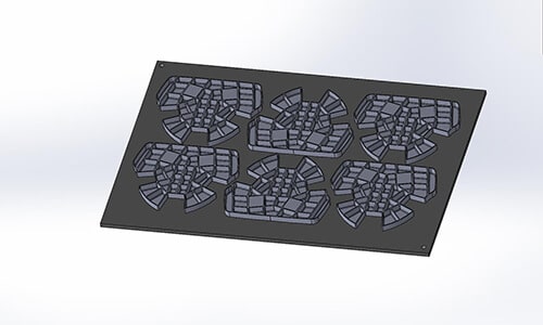
In order to provide a quotation for the piece prices and tooling, our CAD team had to design the tools we would need to compression mold the parts. We utilized the approved CAD model of the actual pad to derive the tool design. The tool model is essentially the negative image of the part.
Because of the heat and pressure inherent in the compression molding process, we design most tools to be machined from 6061 aluminum.
More complex matched tools can also require machined and hardened A2 steel plates to serve as a surface to cut against. In this case, only machined aluminum tool cavities would be required to mold this part.
The Engineer/Develop phase of our product development process also includes determining which foam materials will provide both optimal functions and be as cost-effective as possible.
In this particular case, our customer simply told us which materials had been used to mold this part in the past and we chose a very similar material from the foams that we already stock.
Our customer issued a purchase order for prototype tooling and prototype molded helmet pads. We then proceeded with the machining of the aluminum tool.
When the machining of the tool component was complete, it was incorporated into our proprietary tool base system which allows us to mold and cut most parts in one operation.
Our R & D engineers then set the tool up in one of our hydraulic presses and used the tool to compression mold prototype parts. The parts were sent to our customer for evaluation and approval. The customer was very pleased with the part aesthetics and more importantly the fit and function of the helmet.
Our customer thoroughly evaluated and tested the helmet pad prototypes in order to ensure that they performed as required. Once the prototypes were approved, the customer issued a purchase order for production tooling so that we would be equipped to mass produce parts for their product launch.
We then proceeded to build a multi-cavity production tool. This required that we have several more tool cavities machined out of 6061 aluminum. When the additional cavities were complete, the expert craftsmen in our tool shop assembled them into our proprietary tool base. Our R&D team used the new production tool to compression mold the first article parts for customer approval. The first article parts were approved by our customer soon thereafter.
You can observe the machining process of the prototype tool in this video.
Our new customer was very pleased with how we were able to reverse engineer the helmet pad geometry, design and build a prototype tool and then compression mold prototype parts; all within a 4-week timeframe.
We then built the production tooling for this pad and have been manufacturing these pads for several years. Since then, this customer has had us develop other molded foam hockey helmet pads for their product line. The relationship has developed into a mutually successful partnership and we look forward to continued growth with this customer.

Contact us
Please contact Flextech if you have an idea for a new product you would like to develop, or a problem you would like our sales and engineering experts to help you solve. We look forward to an opportunity to work with you.